![Charged conductors of a parallel-plate capacitor [3].](https://ds055uzetaobb.cloudfront.net/brioche/uploads/zfFF1Cr5Y8-capac.png?width=1200)
Capacitors are physical objects typically composed of two electrical conductors that store energy in the electric field between the conductors. Capacitors are characterized by how much charge and therefore how much electrical energy they are able to store at a fixed voltage. Quantitatively, the energy stored at a fixed voltage is captured by a quantity called capacitance which depends entirely on the geometry of the capacitor (the physical configuration of conductors).
Rapid energy discharge from a very large capacitor via heat and light, leaving scorch marks on a small piece of metal [1].
Capacitors are widely used in circuits for the interesting properties that result from charging them up to a certain potential difference. If a circuit is driven by a battery, the battery will charge capacitors until the voltage across the capacitor perfectly opposes the voltage from the battery, resulting in an effective open circuit in which no current flows. As a result, in steady-state capacitors block direct current, although they are transparent to high-frequency alternating current which does not fully charge the capacitor. Combined with inductors, capacitors are also an essential part of LC circuits, where they cause direct current to oscillate over time.
If two isolated conductors are charged while remaining an overall neutral system, one conductor will have charge \(Q\) while the other has charge \(-Q\). As a result, there will be a potential difference \(V\) between the conductors. Because there is a potential difference between the conductors, the work used to separate the charge onto each conductor is stored in an electric field between the conductors. This overall neutral system of isolated charged capacitors is the most common physical setup for a capacitor. The capacitance \(C\) in such a system is defined as \[Q = CV.\] The capacitance is defined to be positive, so the potential difference \(V\) between the plates is to be taken in the positive direction.
Measured in terms of coulombs per volt, the unit of capacitance in S.I. units is the farad \(F\): \[1F = 1\, C/V.\] In the CGS unit system commonly used in electromagnetism, the unit of capacitance is the centimeter, representing the fact that the exact form of the capacitance is purely a consequence of the geometry of the conductors involved.
Charged conductors of a parallel-plate capacitor [3].
The surface charge density on each plate is \[\sigma = \pm \frac.\] From Gauss' law on a rectangle containing one plate, the electric field due to one of the plates is \[E (2A) = \frac \implies E = \frac.\] The field must be doubled since both plates contribute in the same direction due to the opposite charge. Now using the formula for the voltage in a constant field, \(V=Ed\), the potential difference between the plates is \[V = \frac.\] The capacitance can now be read off from the definition \(Q=CV\): \[C = \frac = \frac. \ _\square \]

Cross-section of concentric spherical conducting shells.
If the two concentric conducting shells are neutral overall, without loss of generality let the inner shell have charge \(Q>0\) and the outer shell have charge \(-Q\). By Gauss' Law, the field between the shells is caused only by the charge from the inner shell, which by the shell theorem is just \(E = \frac<4\pi \epsilon_0 r^2>\), with corresponding potential \(V = \frac<4\pi \epsilon_0 r>\).
The potential difference between the two shells is therefore \[V = \frac <4\pi \epsilon_0>\left(\frac - \frac\right) \implies Q = \frac<4\pi \epsilon_0 ab> V.\] Reading off the capacitance from \(Q=CV\), \[C = \frac<4\pi \epsilon_0 ab>. \ _\square\]
What is the capacitance of a capacitor composed of two large concentric cylindrical conductors, of length \(L\), inner radius \(a\) and outer radius \(b\)?
Another way of understanding capacitance from the formula \(Q=CV\) is that the capacitance is the amount of charge required to raise the electric potential of a system of conductors by one in some system of units. Suppose then that there exists one isolated conductor that begins in a neutral state. Putting any charge on this isolated conductor requires work, since it will create an electric field with potential energy. Therefore, one can define the self-capacitance of a conductor as the amount of charge required to raise the electric potential (with respect to infinity) by one in some system of units. One can think of the self-capacitance of a conductor as the usual capacitance where the second conductor has been taken to infinity.
The electric potential of a charged sphere with the zero point of the potential set at infinity is \[V = \frac <4\pi \epsilon_0>\frac \implies Q = 4 \pi \epsilon_0 R V.\] From \(Q=CV\), the self-capacitance is \[C = 4\pi \epsilon_0 R. \ _\square\]
Storing charge on the isolated conductors of a capacitor requires work to move the charge onto the conductors. By definition of the potential difference, if charge \(dQ\) is added to one of the conductors, causing a potential difference \(dV\), then a work of \(dW=VdQ = \frac dQ\) is required. So the total work required to charge one of the conductors from neutrality up to charge \(Q\) is
\[W = \int dW = \int_0^Q \frac dQ' = \frac.\]
By the law of conservation of energy, the work done in charging the capacitor is stored as potential energy \(U\) in the electric field of the capacitor. Using \(Q=CV\) this can be rewritten several ways:
\[U = \frac = \frac12 CV^2 = \frac12 QV.\]
Energy density or Energy per unit volume of a parallel plate capacitor is \[\bar < U >=\fracCV^2> =\frac\frac (Ed)^2>=\frac\epsilon_0 E^2\], where \(E\) is the electric field between the plates of the capacitor.
As computed above, the capacitance of the parallel-plate capacitor (area \(A\), plate separation \(d\), charge \(Q\)) is
\[C = \frac.\]
Plugging into the formula for the potential energy stored in a capacitor,
\[U = \frac = \frac.\ _\square\]
\[-\frac<4\pi \epsilon_0 b^2>\] \[-\frac<4\pi \epsilon_0 ab>\] \[-\frac<8\pi \epsilon_0 b^2>\] \[-\frac<8\pi \epsilon_0 ab>\]If a capacitor is composed of two isolated conductors, after charging the oppositely charged plates will experience a Coulombic attraction. Given a spherical capacitor of inner radius \(a\) and outer radius \(b\), find the attractive force exerted on the outer conductor assuming that each conductor holds charge \(\pm Q\).
Assume the conductors are mechanically held fixed, so the force is constant in time, and let negative forces correspond to attraction and vice versa.
The capacitance of a capacitor and thus the energy stored in a capacitor at fixed voltage can be increased by use of a dielectric. A dielectric is an insulating material that is polarized in an electric field, which can be inserted between the isolated conductors in a capacitor. That is, when an electric field is applied to a dielectric, the positive and negative charges in the insulating material shift slightly from their neutral equilibrium, creating a small electric field opposing the applied field.
Mathematically, the effect of a dielectric is to modify the permittivity of free space \(\epsilon_0\) by some constant:
\[\epsilon_0 \to \epsilon = \kappa \epsilon_0.\]
The constant \(\kappa\) is often called the dielectric constant, and takes into account how the presence of the dielectric modifies the strength of the electric field in the insulating material. In vacuum, \(\kappa = 1\); otherwise, \(\kappa > 1\) since any atoms present may be slightly polarized.
![Dielectric material between the plates of a parallel-plate capacitor is polarized by an electric field and reduces the potential difference between the plates [4].](https://ds055uzetaobb.cloudfront.net/brioche/uploads/7z3cnfOMZD-capacdiel.png?width=1200)
Dielectric material between the plates of a parallel-plate capacitor is polarized by an electric field and reduces the potential difference between the plates [4].
The capacitance of the parallel-plate capacitor was derived to be
\[C = \frac,\]
with \(A\) the area of each plate and \(d\) the plate separation. With the dielectric inserted, \(\epsilon_0 \to \kappa \epsilon_0\). The resulting capacitance is
\[C = \frac.\]
Since \(\kappa > 1\), inserting the dielectric increases the capacitance and therefore increases the energy stored at a fixed voltage. \(_\square\)
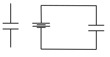
Left: the circuit diagram symbol for a capacitor. Right: a capacitor in series with a battery.
If a voltage is applied across a capacitor where the conductors are no longer isolated but rather connected (e.g. by a wire), charges will move through the potential difference to charge up each individual conductor. For instance, consider a battery with each terminal connected to the opposite faces of a parallel-plate capacitor. The voltage of the battery causes a current that builds up negative charge on one face of the capacitor. The resulting electric field causes negative charges to move away from the opposite face of the capacitor, leaving it with a net positive charge. This charge redistribution creates a voltage in the opposite direction, which changes the current flowing in the circuit and therefore changes the rate at which the capacitor charges. Below, this heuristic analysis is made quantitative.
The voltage across the capacitor depends on the amount of charge that has built up on the plates of the capacitor. This charge is carried to the plates of the capacitor by the current, that is:
\[I(t) = \frac.\]
By Ohm's law, the voltage drop over the resistive wire as a function of time is \(V(t) = RI(t)\). Furthermore, the voltage across the capacitor is \(V(t) = Q(t)/C\) from the definition of capacitance. According to Kirchoff's voltage law (closed loops), the sum of voltages the circuit is therefore
\[V - IR - Q/C = 0.\]
Note the signs in the above equation: there is a voltage drop over the resistor, and the voltage across the capacitor opposes the applied voltage. Substituting in for the current, this is therefore a differential equation for the charge \(Q(t):\) \[R\frac + \frac Q(t) = V.\]
The inhomogeneous equation is solved by \(Q = CV(t)\). The solution to the homogeneous equation is \[Q(t) = e^>.\]
The full solution for the charge, using the initial condition \(Q(0) = 0\), is therefore
\[Q(t) = CV (1-e^>).\]
Differentiating to find the current in the circuit,
\[I(t) = \frac e^>.\]
The capacitor initially charges quickly, but slows down over time. This is consistent with expectation: observe that \(Q(t \to \infty) \to CV\). That is, in steady state the capacitor has charged until the voltage across the capacitor completely opposes the voltage of the battery that is drives the current, so current no longer flows in steady state: a fully charged capacitor acts as an open circuit. \(_\square\)
The energy stored in the capacitor is equal to the energy released:
\[U = \frac12 CV^2.\]
Plugging in \(10 \text< J>\) for the energy stored and \(15 \text< V>\) for the equilibrium voltage across the capacitor, one finds the capacitance:
\[C = 0.089 \text< F>.\ _\square\]
This is a massive capacitor -- small capacitors used in circuits tend to be on the microfarad to millifarad scales.
The most important applications of capacitors are not in direct current (DC) circuits but rather in alternating current (AC) circuits. In AC circuits, the voltage is no longer static but rather sinusoidal and can be represented by a complex exponential with some frequency: \(V(t) = e^\). In this framework, Ohm's law is recast as a complex equation:
where the tildes indicate complex quantities. The physical quantities are extracted by taking the real part of the equation. The quantity \(\tilde\) above is the impedance of a circuit element. Capacitors have an impedance
At high frequencies \(\omega\), the impedance of a capacitor goes to zero. Capacitors are therefore essentially transparent to high-frequency alternating current. This is because high-frequency alternating current rapidly alternates which plate of the capacitor is being charged, so the capacitor never fully charges and the voltage across the capacitor remains negligible at all times. This property of capacitors allows them to filter out frequencies and tune AC circuits to specific frequencies.
Series and Parallel Capacitors:
If multiple capacitors lie in parallel or in series in a circuit, their respective capacitances do not add the same way as resistances but rather the opposite. The total capacitance \(C\) for two capacitors \(C_1\) and \(C_2\) in series or parallel are
There exists a straightforward geometrical heuristic derivation of these facts. First consider two parallel-plate capacitors in a parallel circuit:
Combining capacitors in parallel into one larger capacitor with twice the plate area.
In parallel, the path-independence of the electric potential implies that the potential across both capacitors is the same. Therefore, as above, the capacitors may be placed next to each other without affecting the current or voltage across either. Effectively, this creates one larger parallel-plate capacitor with larger plate area. Since the capacitance of a parallel-plate capacitor is
and effectively the new capacitor has area \(A_1 + A_2\), the new capacitance is \(C_1 + C_2\), consistent with the sum rule for parallel.
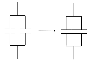
In series, the derivation is analogous. Consider eliminating the wire connecting the bottom and top plates of each capacitor:
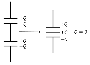
Combining capacitors in series into one larger capacitor with twice the plate separation.
Since the inner plates neutralize each other, this essentially creates one larger capacitor with larger plate separation. From the formula for the capacitance of the parallel-plate capacitor, if the new capacitor has plate separation \(d_1 + d_2\), the new capacitance \(C\) satisfies
\[\frac
Capacitors in series and parallel
Each capacitor in the above diagram has capacitance \(C\). What is the equivalent capacitance?
\[Q_0 (1-e^>)\] \[Q_0 e^>\] \[Q_0 e^>\] \[Q_0 (e^>-1)\]A capacitor of capacitance \(C\) is charged until its plates contain charge \(\pm Q_0\). It is then hooked up in a circuit to a resistor of resistance \(R\) and allowed to discharge starting at time \(t=0\). Find the charge on the capacitor as a function of time, \(Q(t)\).[1] GIF taken from https://www.youtube.com/watch?v=EoWMF3VkI6U using GIPHY.com.
[2] Purcell, E.M. Electricity and Magnetism. Third Edition. Cambridge University Press, 2013.